Introduction
The purpose of this project is to attempt my first sim to real control policy using RL. I will be covering a few of the methods from a workflow I’ve been using. This project is a work in progress and at the present, I’ve produced a model based on commercially available, off the shelf parts. This model has been successful in sim and I’m currently trying to figure out how to execute this code on a Nvidia Jetson.
Picking Some Parts
I’ve chosen parts that are affordable, easy to use, have decent documentation, and are compatible with the Nvidia environment. Additionally Dynamixel has CAD models of their actuators which will help when designing my robot.
The Brains
Have one laying around from another project
Actuation One of the following servos. The difference between the following models is the gear ratio. This is a speed ~ torque trade off
This contained hub pieces that were useful mounting features. Honestly these should come standard… but they are extra…
Creating the URDF with Solidworks
I plan on building this robot so designing with tools like Solidworks makes a lot of sense. I’ll be able to have solidworks calculate parameters like center of mass and inertial tensors for the parts I am using. Additionally there is an amazing tool I want to show that allows you to generate URDF files from Solidwork Assemblies.
Step 1 : Gathering the CAD models
This part is easy, we can find models for the actuators we’ve chosen on the XL330 product website : Actuator CAD. For this project, I’ll be downloading the STEP model for the XL,XC-330
And not that we need it to start, but we can also get a model of the Nvidia Jetson Development Board : Jetson CAD. You will need to log or sign up for a Nvidia account to access this model
Step 2 : Importing the CAD models
Open the XL,XC-330.stp file with Solidworks.
A new Solidworks Document prompt will appear. Select Assembly and continue.
Save the assembly so we can access these parts more easily. All the parts of the assembly will be saved as well so choose an appropriate directory for all the files to be in.
Step 3 : Adding reference geometry
To make life easier down the road, we will be adding in some reference geometry to the actuator assembly. Specifically we want to add :
A point for the origin
An axis to defines the rotational axis.
We want to specify these for the URDF exporter. It has an ‘auto’ mode which often doesn’t make the most correct assumptions about the assembly.
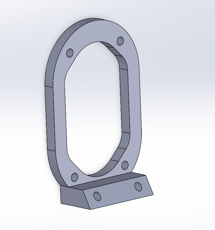
Step 4 : Designing some parts
I need to connect theses servos together so I’ll need to design some parts.
A way of connecting servos together
An arm piece
A base that offsets the next rotation axis with no rotation
A base that offsets the next rotation axis with a 90 degree rotation
A Body type piece
For now I will be modeling this as a box as a placeholder for the Nvidia Jetson
A foot type piece
I won’t go into great detail here but the final results are available to inspect in the repository.
Like the servos, I’ve added a point for CM in the body part. This will be the root of the robot.


Step 5 : Assemblies and Sub-Assemblies
I’ll be using subassemblies for pieces that need to be repeated a lot. This saves time and helps speed up part iterations as well. Changes to sub-assemblies will cascade into the full assembly. I found this useful while designing the robot. Again I will not go into great detail here but the files will be available in the repository.
Servo with 0 degree connector base
Servo with a 90 degree connector base
A Single Leg
The full robot
Step 6 : Redefining Origins and Axis
The URDF converter only likes to use reference geometry from the current assembly file. We will define these geometries by referencing the subassemblies. (Remember when we added the origin and rotation axis to the original servo assembly file)
Note : SolidWorks will throw an error if you create reference axis that are colinear. This is highlighted in the ‘Creating Ref Axis’ video. This isn’t a big problem since we can reuse the reference axis for servos with colinear rotation axis in the default configuration.
Defining the link Coordinate Systems
Defining the joint Rotation Axis
Step 7 : Using the URDF Exporter
The URDF exporter is an add on that will help take our robot assembly and convert it to a URDF. We will define the connection hierarchy and input parameters such joint type, range of motion, maximum effort, and maximum velocity. In the video you’ll see me close and open the URDF exporter tool a bunch. The tool seems to sometimes crash a lot but by manually closing it, you can get it to save the work done so far.
7.1 : Defining the Link Hierarchal Structure
7.2 : Configuring the Link Options
7.3 : Assigning Meshes from Assembly
7.4 : Setting Joint Parameters and Saving
Need to fill in values for limits
lower (rad)
upper (rad)
effort (Nm)
velocity (rad/sec)
Inertial Properties are calculated automatically but can be edited if needed
Done with Solidworks!
Step 8 : A quick import test with Isaac Sim
This is probably the easiest way to see if our work up till this point :
Bonus : Testing Hardware
I’ve 3D printed the parts and assembled one leg with the XL330-M077 servo and another with the XL330-M288 servo. I’ve gotten some code running on the Jetson that lets me set the target angles for the servos position controller.